Op Amp Subtractor Circuit Diagram
Apply two different signals (dc/ac ) to the inputs. An ideal op amp has the following characteristics: When the normally open (no) button s1 is pressed, the op amp is powered by the two 9 volt batteries.
Review of op amp circuits
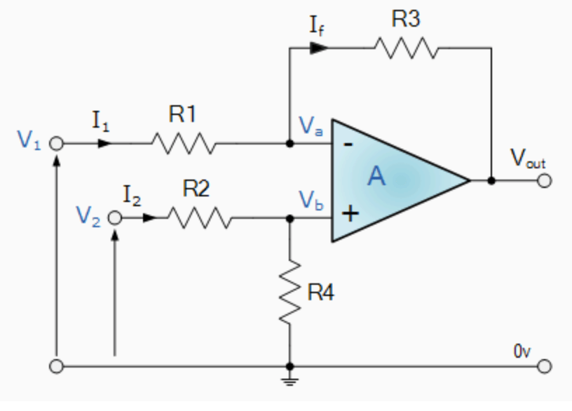
Op Amp Subtractor Circuit Diagram. An ideal op amp has the following characteristics: Due to virtual ground concept, the inverting terminal appears to be at the same potential 'v' as shown in the circuit diagram. Web operational amplifier circuits as computational devices so far we have explored the use of op amps to multiply a signal by a constant.
An Ideal Op Amp Has The Following Characteristics:
Op amps (first edition) message from the editors: Web operational amplifier circuits as computational devices so far we have explored the use of op amps to multiply a signal by a constant. Battery voltage measurement with op amp general electronics.
A Basic Differential Amplifier Can Be Used As A Subtractor As Shown In The Above Figure.
The input signals applied are v1 and v2. The cmrr of a difference amplifier is dominated by the tolerance of the resistors. Web subtractor using operational amplifier if all resistors are equal in value, then the output voltage can be derived by using superposition principle.
These Questions & Answers Will Help You Master The Topic!
Instrumentation amplifier circuit diagram using op amp. Immediately at the output of the integrated circuit (pin 6) there is a high voltage level. For this, eliminate v 2 by making it short circuit.
Apply The Supply Voltages Of +15V To Pin7 And Pin4 Of Ic741 Respectively.
If the input resistors are equal in value (r1= r2= r) then the summed output voltage is as given and the gain is +1. Due to virtual ground concept, the inverting terminal appears to be at the same potential 'v' as shown in the circuit diagram. The supply connections may or may not be shown in a schematic diagram.
This Voltage Is Applied To A Voltage Divider Made Up Of Resistors R2 And R3, And A Reference Voltage Is Set At Pin 3 (Non.
Below, you can see a pin diagram of a typical op amp. Web op amp practical considerations operational amplifiers electronics textbook. I need to create a subtractor on lt spice using an lt1028a to emulate the difference between 90v and 23v;
Web The Proposed Method Solves The Problems Associated With A Conventional Eye Gaze Input Method.
Vary the input voltages and note down the corresponding output at pin 6 of the ic 741 subtractor circuit. It is also called as difference amplifier. 3 apply the inputs v1 and v2.
The Feedback Resistor R F.
Web most op amps are designed to work with two supplies usually connected to positive and negative voltages of equal magnitute (like the ua741 which works with 15v). Subtractor using op amp or difference amplifier circuit. Diffeial amplifier or voltage subtractor circuit.
Web Modified 2 Years, 9 Months Ago.
Ensure that the inputs of the op amp do not exceed the Web subtractor using op amp or difference amplifier circuit: It is also called as difference amplifier.
The Input Signals Applied Are V1 And V2.
How inputs are subtracted and amplified is made clear in this video. Use the op amp in a linear operating region. For the inverting amplifier the multiplication constant is the gain − r 2 and for the non inverting amplifier the multiplication constant is the gain 1+ r2 r1.
An Example Is The Lm358.
The subtractor using op amp circuit diagram is shown in the fig. I have tried using a variety of resistance pairs, but in vain. When the normally open (no) button s1 is pressed, the op amp is powered by the two 9 volt batteries.
Such A Circuit Is Called A Summing Amplifier Or A Summer Or Adder.
Web operation of the op amp tester. Web take the summer and subtractor opamp circuits (analog integrated circuits) worksheet. Apply two different signals (dc/ac ) to the inputs.
Connect The Circuit As Per The Diagram.
The subtraction of the two input voltages is possible with the help of subtractor.

operational amplifier Voltage subtractor using opamp Electrical

OpAmp Differential Amplifier (Subtractor Circuit ) All About Circuits

op amp How common mode signal is generated in differential amplifier
operational amplifier Subtractor using opamp Electrical

bakır kronik doku op amp subtractor circuit

Operational Amplifiers Block Diagram Inverting & Non Inverting Op

Review of op amp circuits

OpAmp Difference Amplifier / OpAmp Subtractor (w subtitles) YouTube
