On Off Switch Circuit Diagram
Resistor r3 limits the charging current of c1 to ensure a long. The remote switch is connected with secondary of transformer. It has a relay output that can be used to turn external devices on/off.
daynight on/off switch circuit diagram
On Off Switch Circuit Diagram. Below you’ll find a basic on/off rocker switch wiring diagram as well as an easy to understand illuminated rocker switch wiring diagram so no matter what your needs, after reading this, you’ll want to put switches on all your leds by yourself. The operation of this circuit is the same as the previous relay switching circuit. This, in effect, looks like an open circuit , preventing current from flowing.
Below You’ll Find A Basic On/Off Rocker Switch Wiring Diagram As Well As An Easy To Understand Illuminated Rocker Switch Wiring Diagram So No Matter What Your Needs, After Reading This, You’ll Want To Put Switches On All Your Leds By Yourself.
Although its name is “clap switch”, but it can be turned on by any sound of about same pitch of clap sound. Manual activation is performed through two momentary contact switches. Switches do not all look the exact same, and they can be drawn in a number of different ways.
The Rf On Off Switch Circuit Diagram Is A Versatile System.
However, physical contact with switches may be dangerous if there is any shorting. Project overview as illustrated in figure 1, in this project, you will build a circuit with a switch placed in series with light to enable control of the current flow. The remote switch is connected with secondary of transformer.
Most On/Off Motor Control Circuits In The United States Are Some Variation On This Wiring Theme, If Not Identical To It.
If you don't want that and if you want to simplify the circuit, you can remove m2, rg, and rgs2, then place the switch between m1's gate and ground. The timer activates a relay through a bipolar transistor in order to connect or disconnect the device we want to control. The main component of the circuit is the electric condenser.
When Once Touch The Touch Plate, The Light Is On, Again If You Touch The Light Is Switched Off.
Resistor r3 limits the charging current of c1 to ensure a long. The circuit described here requires no physical contact for operating the appliance. Web pnp collector relay switch circuit.
Web A Simple Ladder Diagram Showing The Interconnections Of All Components In This Motor Control Circuit Makes This System Easier To Understand:
Web simplest soft latching power push switch on/off circuitthis soft latching power switch circuit design contain only two transistor, resistors and momentary p. Once the load is on then remain in this position unless and until pressing again the push button. Web this is the circuit diagram of clap on / off switch.
Push On Push Off Switch Using 4017 This Circuit Is Using A Decade Counter Ic 4017, Which Counts Or Shifts The Output For Each Rising Edge Of Applied Clock Signal.
This circuit uses small transformer, a 6volt filament transformer, which is connected between one of the main terminals of a triac and the gate. Web a clap on clap off switch is an interesting concept that could be used in home automation. Components required 1 x 555 timer ic 1 x 3.3 mω resistor (1/4 watt) 1 x 1 mω resistor (1/4 watt) 1 x bulb with holder (regular or cfl) 1 x 5v relay module (if relay module is not available, then you need the following components) 1 x 5v relay
The Operation Of This Circuit Is The Same As The Previous Relay Switching Circuit.
This circuit is good and ideal for disabled or elderly people. Here is a diagram of a circuit with a switch in it. Web working of the project apply the power supply and connect the circuit as shown in the diagram.
The Circuit Allows You To Operate Your Lighting Or Any Circuit Device Which Use 24V / 3A Maximum Supply, Simply By Clapping Your Hands.
It has a relay output that can be used to turn external devices on/off. Web the following switch diagrams illustrate the most common types of toggle and rocker switch. Web the rf on off switch circuit diagram is an example of this.
In This Relay Switch Circuit, The Relay Load Has Been Connected To The Pnp Transistors Collector.
It works as a switch which makes devices on and off by making a clap sound. Web here is the schematic diagram of the circuit: Web on off latching switch circuit diagram using ic 4017,555 a push on push off latching switch can use to on and off the load alternatively with the same push action.
Web Automatic Power Off Circuit Diagram.
Web the circuit diagram for the touch on and off switch circuit is shown in the below image. To turn the gadget “on,” place your finger on the “on” plate, and to turn it “off,” place your finger on the “off” plate. Web a switch is a component of an electric circuit that makes or breaks the circuit, turning the components on and off.
They Are Independent Of Each Other And Could Be Of Different Voltages.
Web in the off state, a switch looks like an open gap in the circuit. This, in effect, looks like an open circuit , preventing current from flowing.

Circuit Diagram Day Night Switch Wiring Diagrams Nea

Clap Switch Circuit Diagram Using 555 And 74LS74 Clap ON Clap OFF

Economical On/Off Power Switch Schematic Circuit Diagram
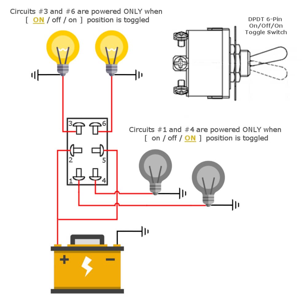
6 Pin Momentary Switch Wiring Diagram Wiring Diagram Schemas

daynight on/off switch circuit diagram

Touch ON OFF Switch Circuit for Appliance using 555 Touch Switch

sound operator on off switch circuit diagram

Switch In Circuit Diagram 3 WAY SWITCH WIRING DIAGRAM Unmasa Dalha
